A few months ago, I got my hands on
ESP8266 Black cloud features Board T5 which has an ESP8266, an 8051 microcontroller and a few sensors. The 8051 microcontroller acts as a master to the ESP8266 and comes loaded with a demo program which is supposed to work with some android app. ESP8266 can be directly programmed using Arduino, so it would be better if I would reprogram the 8051 to act as a slave connected to ESP8266. The ESP8266 will run an Arduino sketch (that I would write) and ask the 8051 for the sensor readings (over UART). To do that I would need to program the 8051 with come C program that I have written.
So the first step was to learn how to compile a simple blinky program for the 8051 and be able to download and run it on it.
Links:
- Black Board T5 User guide (in Chinese) explain how to use the android app (Translated version)
- Reworking the AI Thinker "Black board T5
- Schematic of Black Board T5 (You will need Batang font to view it)
- Source code (Keil uVision project) of the original code running inside 8051
- Datasheet of STC15L2K32S2 (The 8051 Microcontroller present on Black board T5)
- Android app and its source code
- Keil C51 Evaluation Kit ver 9.57 - C compiler for 8051
- Windows utility (stc-isp-15xx-v6.86I.exe) to program the flash memory of STC15L2K32S2 over its UART. The utility is in Chinese so you have to feel your way around it.
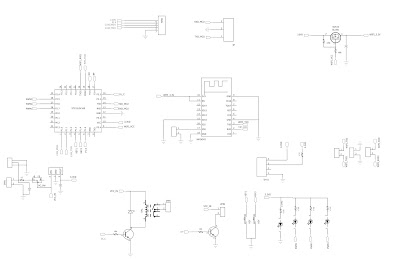 |
| Schematic for Blackboard |
STC15L2K32S2 has two UARTs (Serial Ports). One is connected to ESP8266 and the other one is brought out on the 3 pin header. The one brought out on the 3 pin header can be used to reprogram the microcontroller using the STC's ISP utility (In System Programming)
I used a USB-Serial convertor to connect 8051's UART like so:
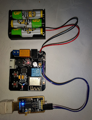 |
| TxD, RxD, GND from CH340 board connected to Blackboad T5's R,T,G Signals respectively |
To run blinky on 8051, I performed the following steps:
- Installed Keil C51 Evaluation Kit on my Windows Laptop
- Connect the USB-Serial board to Blackboard
- Install drivers for CH340 present on my USB-Serial board
- Use the STC utility to install headers for STC microcontrollers to Keil. Keil doesn't come with support for STC microcontrollers built-in.
- Use the STC utility to generate demo code for controlling PWM on STC15L2K32S2. Instead of copying the C code, click "Save project" to save a Keil C51 project - that way all the settings are exported as well.
- Open the project in keil and build the project by pressing the F7 key. Hex file will be generated. The evaluation version is limited to generating 2kB of code, which is fine if you just want to blink LED using the PWM feature of STC15L2K32S2.
- Go back to STC utility, select the MCU type as STC15L2K32S2
- Select the appropriate COM Port
- Load the hex file onto the STC utility (click Open Code File)
- While the Black board T5 is connected to your computer via the CH340 board, keep the batteries installed in Black board T5 but keep it powered off
- Click on "Download/Program" in STC utility
- Turn on the power via the slide switch on the black board and watch the program download.
- Once the program is complete, the code will run and LEDs will fade in and out.
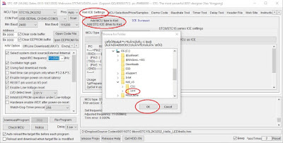 |
| STC Utility: Install headers for STC microcontrollers to Keil |
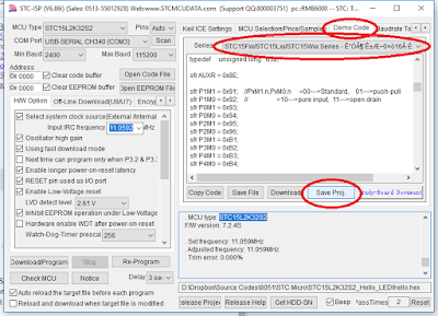 |
| STC Utility: Generate demo code |
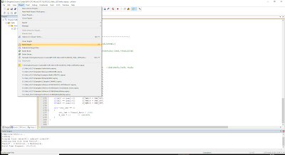 |
| Keil C51 Evaluation kit: Build the program to generate hex file |
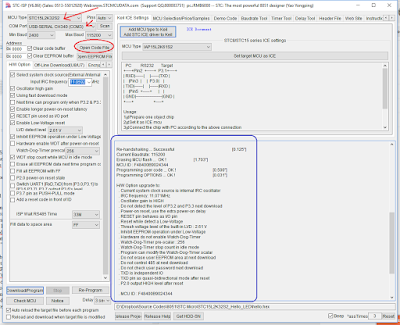 |
STC Utility: select the correct microcontroller, com port,
load the hex file and click Download/Program |
Incase you aren't able to generate code from the STC utility, here is the link to the code (Keil C51 project):
STC15L2K32S2_Hello_LED.rar


Comments
Post a Comment