Contest Buzzer System (by re-purposing Sparkfun's Arduino based 7 Segment Serial Display)
Quiz contest's are one of the most fun ways to learn things in a group. Throw in a buzzer system and you have sense of urgency, excitement and teamwork surging through the various teams.
Couple of years ago (in 2006) - before Arduino or microcontrollers - me and Ranjit assembled a parallel port based buzzer system. We had 5 buzzers for upto 5 teams - we used the 5 Status pins (nACK, Busy, Paper Out, Select and nError) of the parallel port to read the status of the switches. The project lasted us a long time - till the time they stopped equipping laptops with parallel ports!
Some of the features of this system were:
- Use of bell switches as buzzers. the spring action, brings the switches back to off position.
- Use of microphone coaxial cables - these sturdy yet flexible cables are designed to be stepped upon and still last long!
- Use of RCA connector to attach and detach buzzers - essential because we were using coaxial cables
- Pull up resistors to make sure the status pins idled at logic high when the switch weren't pressed. Pressing the switch grounded the corresponding status pin.
- The "Always on top" Visual Basic application which changed color and showed which team pressed the buzzer first - This went well with our quiz sessions hosted on a digital projecter using Power Point slide - the audience could see on the screen who pressed the buzzer first!
 |
| The hardware - made of microphone coax cables and bell switches. |
 |
| The Visual Basic application that read the status pins. |
 |
| The buzzer application went well with our powerpoint slide deck - it always stayed on top. |
Fast forward to 2014 - We now have Arduino and portable power banks! but I am lazier than ever before, so instead of assembling my own circuit, I picked up Sparkfun's 7 Segment Serial Display Widget which is simply an Arduino enabled AVR microcontroller (ATmega328) with a 4 digit 7 segment display. The microcontroller's firmware allows the display to be controlled via its SPI/UART/I2C interface.
And so connected bell switches to the SPI/I2C pins of the 7 segment serial display using them in GPIO mode and replaced the firmware with an Arduino sketch of my own and I had a standalone buzzer system ready. Oh and I added a hacked portable charger (a.k.a, power bank) to make the system really stand alone. The 7 segment display shows the time sequence in which the buzzers were pressed. The system can be reset using the reset bell switch which is connected to the reset pin of the Arduino microcontroller present on the 7 Segment Serial Display widget.
 |
| Sparkfun's 7-segment serial display widget |
Here are the features of the system:
- Sturdy Hardware: Bell switches, microphone coax cables and RCA connectors - all the goodness carried over from the previous parallel port based system. Used cable ties to act as cable stress relief around the bell switches.
- Avoiding Confusion: Used printed numbered labels to mark the RCA sockets and switches. Used spray paint on the beginning and end of coax cables to help identify the RCA plugs corresponding to various bell switches in case the cables got entangled.
- Pin Map: 4 + 1 = 5 bell switches for 4 teams and 1 for the quiz master to reset the system before every question. The pin connection
Buzzer 1 - SDI/MOSI/PB3/PCINT3 - Digital I/O 11
Buzzer 2 - SCK/PB5/PCINT5 - Digital I/O 13
Buzzer 3 - SS#/PB2/PCINT2 - Digital I/O 10
Buzzer 4 - SDO/MISO/PB4/PCINT4 - Digital I/O 12 - Pullup resistors: 8.2 kilo ohms pull up resistors on 4 GPIOs and the RESET pin to prevent false triggering due to electrical noise. Pressing the bell switches grounds the corresponding GPIO pin which is registered by the microcontroller as a falling edge pin change interrupt. One might think that such long lengths of microphone coax cables would cause false triggering
- Arduino Libraries: 3 arduino libraries are used:
- TimerOne - Library to use the Timer1 in interrupt mode - used to refresh the 7-segment display.
- SevSeg - Library used to drive the 7-segment display.
- PinChangeInt - Use interrupts to detect when switches are pressed
- Interrupt Driven: The software does everything in interrupts: The 7 segment display is refreshed every 0.01 seconds using Timer1 and the buzzer inputs are registered using Pin Change interrupts. The main loop lies idle.
- No debounce required for the switches: Since the pin change interrupts are used.
- Non standard Arduino pins used: If you refer to the schematic of 7 Segment Serial Display, you will note that pins PB6 and PB7 are used. You will need to modify C:\Program Files (x86)\Arduino\hardware\arduino\avr\variants\standard\pins_arduino.h to access these pins from withing Arduino IDE. These pins are used to light up segment E and the decimal points. Refer the source code comments on how to make modifications to pins_arduino.h.
- Power Source: A hacked power bank is used to power the system anywhere. The system draws just a few milliamperes of current which is about a hundred times less than what mobile phones used while being charged from the power bank. So the power bank had to be hacked lest it thinks that it is not being used for charging and automatically turns off. Here is how to hack a power bank to make sure it doesn't turn off while powering a low power DI?y project - it involves replacing the current sense resistor. The power bank supplies 5 volts to the 7-Segment Serial
- Housing: A small easily procurable lunch box.
- Program downloading: The 7-Segment Serial Display can be re-programmed using Sparkfun's FTDI Basic Breakout
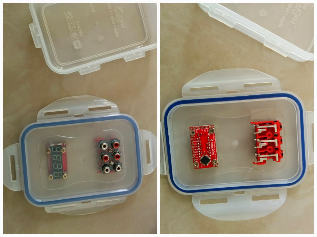 |
| Mounting the 7-Segment Serial Display widget and the 6 way RCA block in the lid of the lunch box. |
 |
| The hacked iBall power bank supplies 5 volts to the Arduino widget. |
 |
| Wiring it all up - note the JST connector, the 8.2Kohms pullup resistors and the blu-tack used to hold the wires in place |
 |
| Nylon Cable ties used as stress relief near the ends of the bell switches. |
 |
| The hacked power bank supplying power to the arduino widget. |
 |
| The complete system. |
 |
| The power bank lies at the bottom inside the lunch box. |
 |
| Using FTDI basic breakout to download a new sketch into 7 Segment Serial Display |
1 2 3 4 5 6 7 8 9 10 11 12 13 14 15 16 17 18 19 20 21 22 23 24 25 26 27 28 29 30 31 32 33 34 35 36 37 38 39 40 41 42 43 44 45 46 47 48 49 50 51 52 53 54 55 56 57 58 59 60 61 62 63 64 65 66 67 68 69 70 71 72 73 74 75 76 77 78 79 80 81 82 83 84 85 86 87 88 89 90 91 92 93 94 95 96 97 98 99 100 101 102 103 104 105 106 107 108 109 110 111 112 113 114 115 116 117 118 119 120 121 122 123 124 125 126 127 128 129 130 131 132 133 134 135 | // This code uses the following libraries each of which need to be downloaded to C:\Program Files (x86)\Arduino\libraries // and placed in a folder of its own. // 1. TimerOne https://code.google.com/p/arduino-timerone/downloads/list // 2. SevSeg https://github.com/sparkfun/SevSeg // 3. PinChangeInt https://code.google.com/p/arduino-pinchangeint/downloads/list // Add non standard arduino pins: // PB6 as digital pin 20 to pins_arduino.h // PB7 as digital pin 21 to pins_arduino.h // To do that // 1. Open C:\Program Files (x86)\Arduino\hardware\arduino\avr\variants\standard\pins_arduino.h with admin rights // 2. Append PB, PB to digital_pin_to_port_PGM[] // 3. Append _BV(6), _BV(7) to digital_pin_to_bit_mask_PGM[] //My buzzer Pinout //RCA Socket 1 - Red - SDI or MOSI or PB3 or PCINT3 or D 11 //RCA Socket 2 - Yellow - SCK or PB5 or PCINT5 or D 13 //RCA Socket 3 - Brown - SS# or PB2 or PCINT2 or D 10 //RCA Socket 4 - Green - SDO - MISO or PB4 or PCINT4 or D 12 #include "TimerOne.h" #include "SevSeg.h" #include "PinChangeInt.h" SevSeg myDisplay; //Create an instance of the object #define RCASOCK01 11 #define RCASOCK02 13 #define RCASOCK03 10 #define RCASOCK04 12 // Struct for 4-digit, 7-segment display // Stores display value (digits), decimal status (decimals) for each digit, and cursor for overall display struct display { char digits[4]; unsigned char decimals; unsigned char cursor; } display; // displays be displays void Timer1ISR() //use Timer Interrupt to refresh the display { myDisplay.DisplayString(display.digits, display.decimals); } void buzzpressed() { uint8_t latest_interrupted_pin; latest_interrupted_pin=PCintPort::arduinoPin; if(display.cursor < 4) { switch(latest_interrupted_pin) { case RCASOCK01: display.digits[display.cursor] = '1'; break; case RCASOCK02: display.digits[display.cursor] = '2'; break; case RCASOCK03: display.digits[display.cursor] = '3'; break; case RCASOCK04: display.digits[display.cursor] = '4'; break; default: break; } PCintPort::detachInterrupt(latest_interrupted_pin); display.cursor++; } } void setup() { myDisplay.SetBrightness(100); //Set the display to 100% bright // Set the initial state of displays and decimals 'x' = off display.digits[0] = '-'; display.digits[1] = '-'; display.digits[2] = '-'; display.digits[3] = '-'; display.decimals = 0x00; // Turn all decimals off display.cursor = 0; // Set cursor to first (left-most) digit int digit1 = 16; // DIG1 = A2/16 (PC2) int digit2 = 17; // DIG2 = A3/17 (PC3) int digit3 = 3; // DIG3 = D3 (PD3) int digit4 = 4; // DIG4 = D4 (PD4) //Declare what pins are connected to the segments int segA = 8; // A = D8 (PB0) int segB = 14; // B = A0 (PC0) int segC = 6; // C = D6 (PD6), shares a pin with colon cathode int segD = A1; // D = A1 (PC1) int segE = 21; // E = PB7 (not a standard Arduino pin) int segF = 7; // F = D7 (PD6), shares a pin with apostrophe cathode int segG = 5; // G = D5 (PD5) int segDP= 20; //DP = PB6 (not a standard Arduino pin) int digitColon = 2; // COL-A = D2 (PD2) (anode of colon) int segmentColon = 6; // COL-C = D6 (PD6) (cathode of colon), shares a pin with C int digitApostrophe = 9; // APOS-A = D9 (PB1) (anode of apostrophe) int segmentApostrophe = 7; // APOS-C = D7 (PD7) (cathode of apostrophe), shares a pin with F int numberOfDigits = 4; //Do you have a 2 or 4 digit display? int displayType = COMMON_ANODE; //SparkFun 10mm height displays are common anode //Initialize the SevSeg library with all the pins needed for this type of display myDisplay.Begin(displayType, numberOfDigits, digit1, digit2, digit3, digit4, digitColon, digitApostrophe, segA, segB, segC, segD, segE, segF, segG, segDP, segmentColon, segmentApostrophe); Timer1.initialize(10000); // set a timer of length 10000 microseconds (or 0.01 sec) Timer1.attachInterrupt( Timer1ISR ); // attach the service routine here pinMode(RCASOCK01, INPUT); digitalWrite(RCASOCK01, HIGH); PCintPort::attachInterrupt(RCASOCK01, &buzzpressed, FALLING); // add more attachInterrupt code as required pinMode(RCASOCK02, INPUT); digitalWrite(RCASOCK02, HIGH); PCintPort::attachInterrupt(RCASOCK02, &buzzpressed, FALLING); // add more attachInterrupt code as required pinMode(RCASOCK03, INPUT); digitalWrite(RCASOCK03, HIGH); PCintPort::attachInterrupt(RCASOCK03, &buzzpressed, FALLING); // add more attachInterrupt code as required pinMode(RCASOCK04, INPUT); digitalWrite(RCASOCK04, HIGH); PCintPort::attachInterrupt(RCASOCK04, &buzzpressed, FALLING); // add more attachInterrupt code as required interrupts(); // Turn interrupts on, and les' go } void loop() { } |
And the buzzer in action in my classroom! Excitement!


Comments
Post a Comment